¿Como crear un reproductor casero de MP3 en una caja de caramelos?
INGLÉS
Overview
There are a few points to be made about making the player, so it's in your best interest to read this section if nothing else.
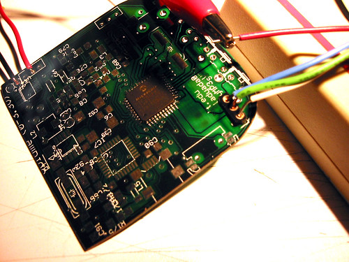
First, the PIC needs to be programmed with the bootloader. You can do this via in circuit serial programming (ICSP), but ICSP runs at 5V and the board should only run at 3.3V. For this reason, you should solder the PIC on, then program it, then continue with the remaining components. You can do your ICSP by soldering the three wires on the top right hand corner (MCLR/PGC/PGD) and another two to VCC and GND (as opposed to BATT+ which goes to the boost regulator). Once you are done you can disconnect the icsp wires.
One of the buttons' legs is in the way of the stereo jack so cut that off with a pair of snips.
Word! Version 2 is up and available. Rejoice!
This is an advanced project, I highly suggest that you don't take on a project like this to 'learn how to solder' or 'how to program a PIC'. If you can't handle fine-pitch SMT or getting boards made, just buy an MP3 player, they're sold in stores nowadays!
If you want to build an MP3 player, try something easier, like the Super Simple MP3 or you can even buy kits for the portable YAMPP-7 via JELU.
Buy or sample all the parts you need
Make the PCB at a reputable PCB manufacturing house. Use a bandsaw or similar to get it into the right shape.

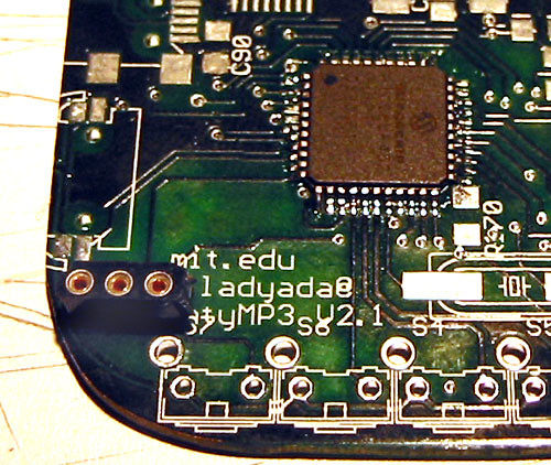
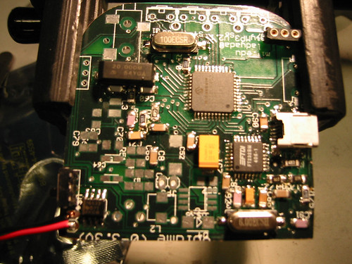
Solder the PIC18LF452 onto the board. Use something like solderpaste or high quality silver solder.

Tacked down mcu with solder paste

Swipe the soldering iron across the pins, or use a Black&Decker 'reflow' oven
Solder a 3-pin SIP header in the top right corner, for programming through ICSP
Make a dongle by soldering 5 wires (pwr, gnd, mclr, pgd, pgc) to a DIP socket
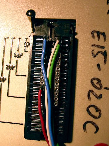
Connect this to your programmer, plug the MCLR, PGD and PGC wires into the header, and use alligator clips or solder to connect power & ground.
Program in the bootloader (or the final firmware if you doubt you'll ever upgrade.) Verify that your bootloader is setup for 29.419MHz.
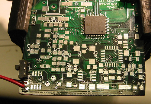
Solder in the power switch, and resolder the power line in the bottom left corner
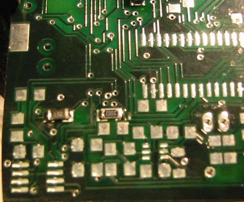
Solder in the two filter capacitors on the back (C31 & C39)

Solder on the microcontroller diode (D2), which is on the other side of the board for the current revision

Solder the regulator (so, actually, I was having problems with it. So if you're going to be running from a lithium ion, and things are flakey, you can just short input and output on the chip) and the large filter cap (C8)
Solder on the 29.419MHz crystal (which might be in a different package) and the two capacitors (C11 & C12)

Connect the circuit up to 3.7V power, turn it on. Verify that the crystal is oscillating at the proper frequency.
The USB subsystem allows us to load code to the microcontroller, and recharge the battery. Solder on the mini-B usb conncetor, the 6MHz crystal and two capacitors (so, actually, in the current version, this has been replaced by a ceramic oscillator that sits on the other side)

Solder the FTDI chip using the same technique used for the PIC micro. Solder on the passives necessary for the FTDI chip (these might have shifted around a bit: R21 thru R25, C32, C33, C35, C37, C42)
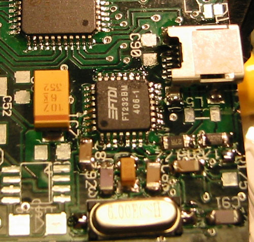

Plug in USB power, your computer should recognize it as a USB to serial converter. Drivers are available from FTDI if they don't come with your OS (most modern ones do)

Use the serial driver and tinybld16 (or, if you have decided on a different bootloader, the proper software) to upload the current MintyMp3 firmware. Turn Minty off and on, and use a terminal program (at 1152Kbps) to make sure Minty firmware is loaded. It should at least print out "Minty MP3! v2 3/25/2004" or something similar
If you're going to run the player off of one or two 1.5V cells, now is a good time to put in the boost supply. Solder in the MAX756, C10, D1, C8, L1, C9 and run wires to JP3 (battery + and -). If you're not putting this part in, just solder in C8. If you want low battery notification (?) solder in LED1. (I've never actually used this so I don't guarantee its functionality. I'm pretty sure it works :)
Test the supply to verify its giving you 3.3V out. Also make sure the PIC is still running at this point.
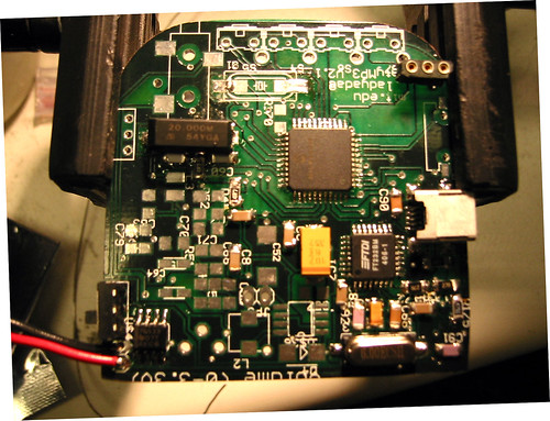

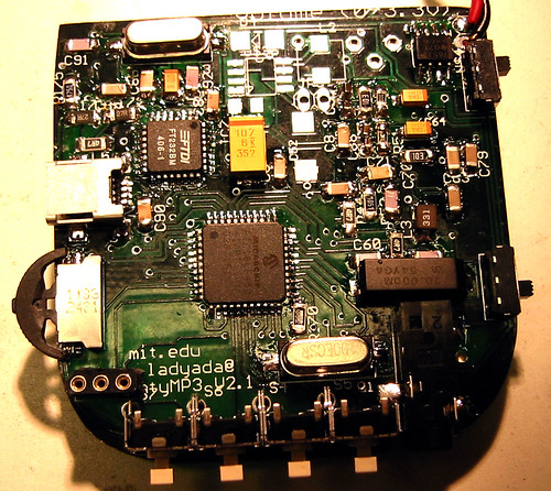
The completed PCB

What's in the box? Pain Minty!
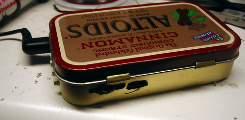
~ Enjoy! ~
Fuente: http://www.ladyada.net
2 comentarios:
-
Este comentario ha sido eliminado por un administrador del blog.
-
Este comentario ha sido eliminado por el autor.


